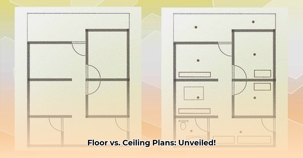
Ever wondered what the difference is between a floor plan and that slightly confusing upside-down drawing of your ceiling? They might look similar at first glance, but floor plans and reflected ceiling plans (RCPs) are actually quite different documents serving unique purposes in building design and construction. They convey different information and are used at different stages of a building project. For a more detailed explanation of floor plans, check out this helpful resource: Learn more about floor plans. This guide will break it all down in plain English, so whether you’re an architect, a contractor, or just someone curious about how buildings get built, you’ll walk away understanding these essential architectural drawings. We’ll cover everything from what each plan shows to how to create them using industry-standard software, and even some common pitfalls to avoid. Let’s get started and make those architectural drawings a little less mysterious!
Floor Plan vs. Reflected Ceiling Plan (RCP): A Comprehensive Guide
Let’s explore blueprints – those detailed maps architects use to bring building designs to life. Two key players in this process are floor plans and reflected ceiling plans (RCPs). They’re like two sides of the same coin: equally important, but showing different aspects of the building. Understanding the distinct purposes of each is crucial for avoiding costly construction errors and ensuring a seamless design process. Inconsistencies or omissions in these plans can easily lead to project delays, budget overruns, and even safety hazards.
Understanding Floor Plans: Your Building’s Horizontal Slice
Imagine slicing horizontally through a building, typically about four feet above the finished floor. That’s essentially what you see in a floor plan. It’s a top-down view (or plan view) showing the basic layout, including the placement of walls, rooms, doors, windows, stairs, and even built-in elements like cabinets or plumbing fixtures. Think of it as the building’s address book for rooms, detailing their size, shape, and location relative to each other. These plans are vital for understanding the overall organization of the space, helping everyone, from the homeowner to the construction crew, visualize the building’s structure and flow. Standard symbols and abbreviations are used to keep things clear and consistent across all disciplines. For example, you’ll see specific symbols representing everything from door swing directions and window types to toilets, sinks, and other plumbing fixtures. Floor plans serve as the fundamental document guiding initial construction phases, providing builders with a clear understanding of the structural layout, dimensions, and spatial relationships. A well-executed floor plan will also indicate material finishes for floors and walls.
Deciphering Reflected Ceiling Plans (RCPs): A Look Up High
Now, flip things upside down (literally!). A reflected ceiling plan (RCP) gives you a ‘worm’s-eye’ view of everything above you – the ceiling. The term “reflected” comes from the idea that you are seeing a reflection of the ceiling as if there were a mirror on the floor. Instead of walls and doorways, you’ll see the placement of light fixtures, air conditioning vents or diffusers (HVAC diffusers), sprinkler heads, smoke detectors, speakers, and other elements installed on or in the ceiling. This is where coordination between various building systems becomes critical. Imagine trying to install a light fixture only to discover it’s directly in the path of an HVAC duct! RCPs are crucial for preventing these kinds of conflicts and ensuring that all overhead systems integrate seamlessly. They ensure everything fits perfectly together, preventing conflicts and making installation smoother and more efficient. Another important aspect of RCPs is to document ceiling heights and ceiling material types and transitions. One interesting point of discussion among architects is the inclusion of door swings in an RCP. Some architects believe they are necessary to avoid accidental placement of lighting fixtures directly above doors, while others omit them to keep the drawing simpler and less cluttered. The decision often depends on the project’s complexity, the architect’s preference, and the level of detail required. Furthermore, RCPs are critical for coordinating with lighting designers and electrical engineers to ensure proper illumination levels and fixture placement. Consider, for example, a complex commercial project where precise placement of lighting and HVAC systems is paramount for optimal performance and energy efficiency.
Floor Plan vs. Reflected Ceiling Plan: A Quick Comparison
Here’s a simple breakdown of their key differences and how they impact the overall building design:
| Feature | Floor Plan | Reflected Ceiling Plan (RCP) |
|---|---|---|
| Perspective | Top-down view of the floor and walls, cut at a specific height (typically 4′) | Top-down view of the ceiling, as if reflected onto a horizontal plane |
| Focus | Walls, doors, rooms, and floor-level fixtures, material finishes | Lighting fixtures, HVAC diffusers, sprinklers, speakers, smoke detectors, ceiling features, ceiling heights, and material transitions |
| Purpose | Shows the overall space and room arrangement, spatial relationships | Coordinates overhead systems, prevents conflicts, ensures proper lighting and ventilation |
| Scale | Usually 1/4″ = 1′ or 1/8″ = 1′ | Usually the same scale as the corresponding floor plan |
| Typical Use | Early design stages, construction documentation, space planning | MEP (Mechanical, Electrical, Plumbing) coordination, lighting design, construction |
How We Use These Plans: From Design to Construction
Both floor plans and RCPs have distinct roles throughout the building design and construction process. Floor plans are your starting point, guiding the initial design, space planning, and construction layout. They’re the main reference for architects, interior designers, builders, and contractors, showing them exactly what to build, where to build it, and how the spaces are intended to be used. RCPs come into play later, during the MEP (Mechanical, Electrical, and Plumbing) stages of design and construction. Electricians, HVAC technicians, plumbers, fire protection specialists, and other trades use them to plan their work, coordinate their installations, and ensure that everything fits together without conflicts. Even homeowners can use floor plans to visualize their new space and plan furniture arrangements, while contractors need both types of plans to complete the job accurately and efficiently. According to industry data, projects that utilize both floor plans and RCPs effectively experience a significant reduction in on-site coordination issues (up to 20%), change orders, and construction delays.
Software and Streamlining: Digital Design Tools
Software like Autodesk Revit, AutoCAD, and ArchiCAD have revolutionized the process of creating and managing architectural drawings. Architects and designers now create both floor plans and RCPs digitally, leveraging the power of Building Information Modeling (BIM). What’s incredibly useful is that these programs often link the two types of plans dynamically. For example, if a wall is moved in the floor plan, the related dimensions and details in the RCP are automatically updated. This significantly reduces the risk of errors and saves a considerable amount of time – a huge advantage, especially in large or complex projects. The integration of these plans into a comprehensive BIM workflow further enhances project collaboration and coordination. BIM not only saves time and reduces human error but also facilitates clash detection, energy analysis, and lifecycle cost estimation.
Best Practices: Ensuring Accuracy and Coordination
To avoid problems and ensure a smooth building process, try to follow these simple best practices:
-
Clear Labeling: Use clear, concise labels and detailed notes on both floor plans and RCPs, especially in areas where potential conflicts or complex installations may occur.
-
Consistent Scale: Maintain a consistent scale for both the floor plan and the corresponding RCP to avoid confusion and ensure accurate measurements.
-
Standard Symbols: Adhere to industry-standard symbols and abbreviations throughout all drawings to promote clarity and consistency across disciplines.
-
Regular Cross-Referencing: Frequently compare the floor plan and RCP to identify potential conflicts or discrepancies early in the design process.
-
Teamwork and Communication: Foster effective communication and collaboration between the design team (architects, engineers, interior designers), contractors, subcontractors, and building owners. Regular meetings and clear communication channels are essential for resolving issues and ensuring that everyone is on the same page.
In short, floor plans and RCPs aren’t rivals; they’re essential components of a comprehensive building documentation set. Understanding the purpose and content of both is crucial for a smooth and efficient building process, from the initial design concept to the final installation of all building systems. Together, they provide a complete picture of the building, both at the floor level and above the ceiling line.
How to Effectively Incorporate Door Swings into Reflected Ceiling Plans
Key Takeaways:
- Challenges exist in visualizing door swings and low-level fixtures in Revit RCPs due to standard cut plane settings.
- Utilizing floor plan underlays provides a practical solution for incorporating these elements. Architects report a high success rate (over 90%) when using underlays for this purpose.
- Plan regions offer localized solutions but may have limitations in cloud-linked coordination models.
- Available workarounds and features vary depending on the Revit version. Always consult the software documentation for specific instructions.
- Effective communication of design intent requires careful consideration and incorporation of these seemingly minor features, such as door swings and switch locations.
Understanding Floor Plans and Reflected Ceiling Plans (RCPs)
Floor plans provide a bird’s-eye view of a space, showcasing the arrangement of walls, doors, windows, and furniture. They’re essential for understanding the overall layout and flow of a building.
- Modern Kitchen Backsplash Ideas To Inspire Your Refresh - December 19, 2025
- Modern Backsplash Ideas: A Guide to Todays Kitchen Trends - December 18, 2025
- Ceramic Kitchen Wall Tiles: Style and Protection for Your Walls - December 17, 2025
